Consciousness and how it all relates "its the big step"
Understanding consciousness and the triangle

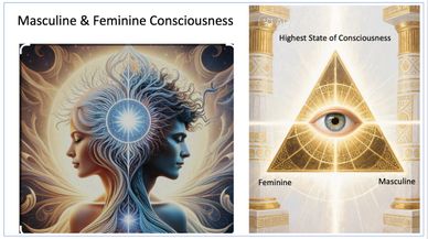
The masculine and feminine part of consciousness along with the highest part of consciousness geometrically form the divine triangle. Understanding this symbolism and concept is the understanding of higher knowledge and awareness. When shown in the public arena this is a form of immense energy alignment for those who understand it. This alignment understanding and recognition create coherence in the field to a desired reality. Some may label this as occultism but fail to understand the truth of higher meaning and consciousness. This failure is a form of institutionalized ignorance and programing set as to limit ones true higher divine ability. The divine power was and is always in you. It is your birth right, claim it and change your reality.
The objective has always been the higher knowledge to the collective
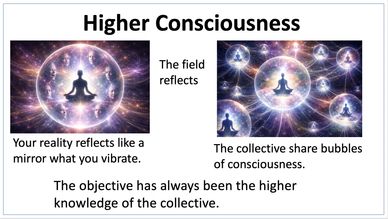
So simple, the objective has always been the higher knowledge to the collective consciousness. The keeper of consciousness the divine. The mirror reflects what you vibrate, your frequency all around you. The collective each consciousness connected experience and discovery each experience in the network. The very fabric of consciousness itself, intricate, ever present, ever experiencing, and updating.
The "Shift" from 3D to 5D Reality
The Masculine and Feminine consciousness with Highest consciousness Triangle
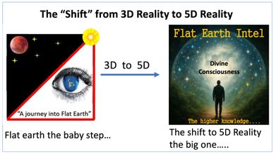
Once you understand how the shift from 3D reality to 5D reality occurs, your never the same, it is life changing. And in 2017 when I was swallowed into divine consciousness that day in Kuwait, I was ignorant of the real understanding of what was occurring at the time. Looking back now I understand now what occurred and why. Each of us has our own journey in this life, understanding the lessons, blessing, gifts as well as failures, tragedies and hard times all give us reality of experience. What were not taught is how to align with the desired reality we want from the very beginning. Once you learn it, its life changing.
The Masculine and Feminine consciousness with Highest consciousness Triangle
The Masculine and Feminine consciousness with Highest consciousness Triangle
The Masculine and Feminine consciousness with Highest consciousness Triangle
The power has always been in you. You were created as part of the divine experiencing this reality with limitation. That limitation was and is program based since your childhood the first decade of your life.
The Power of You is Divine
The Masculine and Feminine consciousness with Highest consciousness Triangle
The Power of You is Divine

The power has always been in you. You were created as part of the divine, experiencing this reality with limitation. That limitation was and is program based since your childhood the first decade of your life. Then as you continue in life your exposed to more by media religion, education system all creating the prison in your mind the ultimate containment cell that's called "the matrix". Learn the truth of who and what you are is the first step away from this programming. The next step is taking your power back. The single greatest threat to not taking your power back remains religion. Spirituality teaches you the power is in you internally, just as Jesus said the kingdom of heaven in within you. Religion teaches you the kingdom of heaven is outside you. External validation. Ask yourself this....where do you stand.
"the Matrix your mind" in simulation the 5D reality shift
The Matrix Simulation
Identify the simulation using the sun
You Unknowingly are your own Capture

The simulation matrix is layered through our own consciousness. It is psychological, emotional and physical. Quantum physics had identified this through in measure the brain waves as well as experiments like the double slit experiment. You create your own reality. It is a complex process of understanding how to feed your subconscious as well as control what information you intake, avoid negative, fear based programing. Your subconscious is most receptive just before sleep and as you wake after sleep.
You Unknowingly are your own Capture
Identify the simulation using the sun
You Unknowingly are your own Capture
You unknowingly are part of your own capture. Your were born into this false reality. The matrix reads your subconscious mind. Your fears, worries, and thoughts are all plugged into the surrounding realty you generate, you are your own script writer. You mirror what you generate in reality. Also plugged into what you see and process, this includes programming through education, media, and what you absorb and process daily. Understanding your frequency and vibration (coherence) are key to altering your consciousness and reality to the desired result, it is understanding the Quantum field. Like tuning in to a radio station that you desire, if its jazz music, you don't tune into a rock n roll radio station, the frequency is different.
Identify the simulation using the sun
Identify the simulation using the sun
Identify the simulation using the sun
Very early on I had an idea that using the sun at different locations on earth (measuring suns height) would identify several things; one identify earths surface shape, the other being it can identify the simulation based on sun position at different locations and elevations described in the diagram.
The Ancient Gnostic's
Identify the simulation using the sun
The ancient Gnostic gnosis or knowledge was very clear on .the samsara wheel reincarnation and what it meant as part of the soul trap system. The cycle of life in this simulation birth - life - death and recycle. It is also applied to civilizations, once they achieve a certain knowledge they are basically removed whether through self destruction of endless wars or other civilization ending plots.
Ancient Gnostic Scripts and Teachings
The Nag Hamadi scripts recovered in 1945 from Nag Hamadi Egypt give insight on what the ancient Gnostic's understood about the Christ consciousness. These writings far differ from mainstream religion. The Apostate of John being one of the most controversial writings. The ancient Gnostic's were hunted down, sects were disbanded and eliminated with great effort.
These scripts posed a direct threat to mainstream religion and control. The teachings of these scripts emphasized inner Christ consciousness. The power is within you and not from an external deity. The Kingdom of God in is within you. It basically taught self power and control not external. This posed the greatest threat to religion and control of the masses.
The Pleroma (Monad)
Ancient Gnostic texts mention this divine realm, source of pure consciousness, truth and light. The triangle symbol meaning the highest state of consciousness and balance.
Three Types of Humans

Understanding the three types of human's and why some just don't get it. They were never meant to. Only some retain the divine spark.
The Sky Grid System

The sky grid system that maybe used to power part of the matrix of your mind. The sun electric the moon magnetic. You unknowingly power the very system that holds you in check.
The Human Toroidal Field

The toroidal field that the human body generates is affected by vibration and frequency.
They Show You to Produce Energy from your own reaction
The energy you produce from emotion, feeling, and vibration is all part of the matrix. The reaction from media produces a energy resonance frequency transmitted into the matrix. In this example they show the "Divine Spark" or in the Movie Series The Transformers its called the ALL Spark. They show you in plain sight. With the rapid advancement of AI there's a big push to create power sources to support AI something to keep an eye on, power generation, humans energy producers maybe replaced.
"The ALL" Pure Consciousness and Light
Our divine spark and the third eye mirror "the ALL", the one. Learn how to program your subconscious to change your reality. Once you program it it must mirror into reality. It takes time and training to learn how. it's why you see celebrities and famous people showing the hand triangle sign. They have mastered how to program their subconscious into reality. It is more than just words or sayings. Essentially, alignment and vibration and emotion, once aligned anything can be achieved. Manifestation is real. The All is part of the Pleroma pure consciousness and infinite light from which ALL things come. You were given a third eye for a reason :)).
Hylomorphism
Hylomorphism what it is and what it does.
Secret Agent Jesus and the Simulation
The Jesus Gnosis
The collect Christ consciousness is believed to breakdown the system. The ancient gnostics mention Jesus and his death traveling the soul trap as part of understanding and experiencing the way out. The soul trap (is the endless cycle of individuals caught in the materialistic world who never evolve to higher astral plane). Call it a trial run that had to be done, enter secret agent Jesus sent from the Pleroma. He needed help someone who would help not only set it up but make sure once the information he obtained was spread on how to get past the soul trap system.. He needed a pilot to assist, enter Pontious Pilate and the plot thickens.
Secret Agent Jesus and the Simulation
The trial run once done by Jesus revealed information on how to get around the soul trap system. Jesus maybe the first Quantum Physicist in recorded history. This information had to be disseminated out carefully before it was found out. The gnostics spread information as well as hid this information later recovered in 1945 in Nag Hamadi Egypt. Highly controversial with mainstream religion who vigorously tried to destroy this information for centuries. Has this system evolved? questions remain. There is a strong belief that the collective Christ consciousness will tear apart this matrix system and break the cycle soul system because of the collective strength in consciousness. This is also known as the great awakening.
Simulation and Your Souls Journey
Your souls on a journey within the simulation, and may actually travel in groups or with your soul partner living each life experience in an earthly realm. Gathering experience, what your soul may lack, what it learned and where it will go next. All information is gathered into the collective. Quantum physics experienced and lived with each soul experiencing a new simulation world as part of developing a complete higher consciousness of the ALL.
Broadcasting out of Want and Need
To obtain alignment and coherence in vibration and frequency don't broadcast out of want or need. Your mirroring that lack into the universe and its reflected right back on you. You are sabotaging your own self. Instead ask the universe what is it your showing me? Or I trust the flow the universe is trying to tell me. Don't send mixed signals
The Rapid Advancement of AI
The rapid advancement of AI issues in a new age or is it an up and coming reset to replace humans, the energy producers being replaced by AI? It makes one wonder how rapid this is all taking place with these power plants being built at record pace. AI the new energy source to replace humans and affect the soul trap.
You are Divine Consciousness
You are the divine consciousness pretending to be limited encased in human form. Jesus declared this "The Kingdom of God is within you", Luke 17:21.
.The kingdom of God cometh not with observation, Luke 17:20. With this we must understand the difference between spirituality and religion. Spirituality teaches the kingdom of heaven is within you, religion teaches the kingdom of heaven is outside you. The difference between internal and external validation.
The Divine Celestial
As part of the Pleroma, the divine celestial Aeons, and Goddess Sophia who was said to have caused the rupture in the universe when she tried to understand more of the divine consciousness Pleroma by creating a being by herself without balance. She created what is called the Demiurge the creator of our reality. The Demiurge however does not have the divine spark because of this violation and is lesser than divine but is ignorant to this.
Whether one is to believe these ancient story's is in ones own thought. The past history has been written on many things, events, and ideas we may look into or question. Or is it all part of an intricately cleverly designed information to let our thought process wonder intellectually.. We may never know the answers to many questions that arise from this information.
The Demiurge
The demiurge said to be created by Sophia, not as malice but in an attempt to get more understanding of the Pleroma the divine consciousness also known as the "Monad". This act created an in-balance a fracture in the balance of the greater universe . As a result the demiurge was created. As a result the demiurge came out looking different The image of the demiurge is said to have the head of a lion and body of serpent. The demiurge according to Gnostic's text is the creator of this universe and earth, the God of the old testament. And rules this realm along with what he created the Archon's or watchers. These are purely limits in frequency range dynamics which can either keep one looping or alignment out of low range frequency to a higher dynamic one. The matrix itself being YOUR mind, its the first hermetic law ALL is mind, the universe is mental. Meaning you contain every reality in your mind. The process is mental coherence to the universe on aligning to desired reality.
The Archons
The demiurge has help, and created the Archon's in this reality. They are referred to as the watchers. They are energy collectors, they require it to operate within the system. That energy comes from human emotion, pain, suffering, sorrow, pleasure, lust, greed, all are energy fuel. Some text refer to the planets the wandering stars as the guardians/archons that guard the SOL (soul) system the sun which is you. They are parasites that feed off of human energy. They are in effect simply frequency barriers that keep one looping in the same reality. These are depicted as pillars in masonic drawings they are left and right limit barriers or high n low frequency rang symbolism.
The Tunnel of Light
In my own personal experience, my grandfather had an after death experience and was told to return it was not his time. There are many accounts both documented and undocumented of these stories. In the end we will all have to make that terminal decision whether or no to go into the light.
NPC's within the Matrix Simulation
NPC's within the Matrix Simulation
The NPCs within the simulation help facilitate the experience and learning process. Some may not fully understand the importance of the entire learning process and how they enhance it.
Keeping it simple
Some Common Word Association with each Model
Some common word associations with each of the models. Some may not agree with this list or how they are listed. I think it gives a better perspective when we can step back and look word alignment with each model. I think there's has been an effort to *blend* certain words into each model over time. But some words just don't fit the model. Example space in the FE model just doesn't fit or creator and the globe model when it is clearly tied to the theory of evolution. The hard reality being heliocentrism will not share its cosmology with Christians, your only fooling yourself if you believe they will. The flat earth biblical cosmology is a reality, this earth being created for us by a creator who loves us. One just needs to be educated and understand how the flat earth model works. Knowledge is power.
In order for the Copernican model to work
In order for Copernicus to verify that the heliocentric model works. Each listed area should have been verified in that models orbital mechanics. Because the sun is the center celestial body for the globe model to which the earth is said to be orbiting around, the suns position becomes the primary validation and focal point. And if we look at the sun we can see the BIG problem for this model with the sun out of position in the daytime sky. The suns height being "to high" becomes a huge problem for this models orbital mechanics. And if your models sun is out of position that model fails as vertical angle testing on both sides of the terrestrial earth have shown. This presents three areas of geometric failure for the globe model. This means the earth isn't orbiting the sun but rather the suns orbiting over a flat stationary earth.
Sun *Position* is the Answer

It's as easy as seeing the sun in either the first story or second story window. The suns position tells the real answer. If the sun is seen in the first story window during late Spring, Summer, and early Fall sun seasons the earths surface could either be flat or curved. As a rule of thumb general times will be (9 - 10 am mornings, and afternoon times 3 - 4 pm).. In this example the sun is in the first story window.
Distinguishing earths true surface as flat
In this example of the two story house the sun is in the 2nd story window. This distinguishes earths true surface shape as being flat. This is because in the designated sun seasons and times the high sun position can only be viewed from a flat surface. Finding out the why is the *NEXT* step.
How the Heliocentric model works against itself
The globe model has many faults most of which work against itself. Distances for this model from earth to the sun work hard against this model based on its measured vertical angle to the sun. This means once the limit for this model is "exceeded" the farther out you go the worse it gets for this model exceeding the line of parallel. The lines of parallel are; line one being the sun at 90 degrees, and line two being the measured sun height from the OS. The "equatorial plane" is next, this being the globe actually tilts to maintain the sun at 90 degrees within a belt surrounding the globe model. This is this models "Achilles heel" and its most vulnerable area. Knowing the limit for this model based on measured sun heights at the OS makes this a very short conversation once "the limit" for this model is exceeded. But you first have to know how to get the limit.
Understanding the *WHY* the high sun is the real answer
Understanding sun location in our daytime sky or the high sun is primary evidence of flat earth. And it is why the sun, once we understand its position in the sky only works in ONE model the geocentric flat earth model. At 46 degree or more the earths true surface shape distinguishes itself as flat at observation times of 09:00 - 10:00 am and 15:00 (3pm) - 16:00 (4pm) daily. Like a window in the sky as shown in the diagram above the sun position in the sky verifies the difference between a flat or curved surface. This is because the object of reference the sun when sighted center mass has now exceeded the line of parallel, and you are no longer sighting on the sun center mass (proper earth to sun alignment is exceeded) for the globe model. At 45 degree and below the earths surface is indistinguishable between flat and curved. The most difficult times for the globe model are the summer season, inside the prime meridian zone and low altitude, this is because the globe model only has 45 degree upper surface measurement to work with because the observer is at a 45 degree surface angle to the sun which reaches line of parallel for the globe model at 90 degree.
The Vertical Angle using the Sun will give us the answer to earths true surface shape
Keeping it simple. Measuring the suns height (vertical angle) will give us the answer to earths true surface shape. And its why the sun has to be 45 degrees or less for the 45 degree sector test. The simple math of it is not complex. Simply add the observer angle (1) at the time of observation this is also known as the surface angle + the measured sun height (2) to give us the sum (3). As shown in the above example 45 + 45 = 90. The sun is always 90 degrees in the tropics which is the limit. The observer angle (surface angle) can be checked by performing a sun plot (step 6) in the 9 step geometric validation process which is explained on this page. Best testing times are during the summer solstice. This is because the sun is at its maximum zenith when its closest to the observer and the most difficult time for the globe model to pass. In other words this model cant hide behind distance alone, it must prove itself by position height to be valid which lends directly into the models orbital mechanics.
How to measure distance and surface angle on the globe model
In this slide we can show how to measure distance between the OS and the suns position in the tropics (equatorial plane) as well as surface angle. Because the geometric form or shape is a sphere distance equates to surface angle for this model. Each latitude and longitude grid on this globe is 10 degrees in scale size. That means 10 degree across whether left to right, right to left, up or down, down or up, or diagonally. In this example a distance of 55 degrees is shown between the observer at the OS to the suns location in the tropics by simple math addition. This distance of 55 degrees equates out to a surface angle of 55 degrees as well. Meaning the observer is 55 degrees to the sun at the time of observation. Also note the red circle "ring" being 360 degrees shown and how the breakdown of the geometric shape can be accomplished. Keeping it simple.
Measuring the suns height the limit and vertical angle the line of measure from the OS
Using Solo Timed Observation (STO) as in this example or Simultaneous Observation (SIMO), along with the Marx device, compass, and a digital protractor we can create a grid pattern to check the suns position with regards to both the globe and flat earth models. This grid is then used to verify whether the observation station (observer) is viewing the sun from a flat or curved surface. This essentially creates accountability within the system. Simply measuring the suns height (vertical angle) as shown can give us the answer to earths surface shape. Because understanding the the suns position our daytime sky is the real answer to determining earth's true surface shape, learning how is why I have developed this website. Keeping it simple.
Understanding the "Effect" of "Vertical Angle" and when its exceeded
Understanding the "Effect" of "Vertical Angle" and when its exceeded
Knowing the limit. This civil engineering example of bridge height. Probably the easiest to understand when vertical angle is exceeded in everyday life is the bridge height example as shown. Semi-trucks are standard height of 13'6". This means any bridge they travel under must be at least 13"6" in height or higher as shown on the right side of this example. On the left side of the slide example is a bridge height of 12'4" in height which is to low for the semi-truck to pass under. The result will be an accident and damage to the truck and bridge. Understanding the effects of vertical angle, keeping it simple.
The 9 Step Geometric validation process setup for testing
Step 1 Equipment Required

Equipment required as shown. Always ensure to use eye protection when viewing the sun. Equipment used was based on ease of use, cost and being effective. Total cost was around $200.00 USD. Identifying the OS test equipment required to conduct direct sun angle measurements. This is used for testing the 45 degree sector.
1.The OS platform is a white dry erase board. 2.The digital protractor runs on 9volt battery 0-225 degree with .5 degree accuracy. The protractor also has a level bubble.
3.Tape measure for measuring OS platform height.
4.Sun shield for eye protecting when viewing the sun (should be used with sun glasses as well). 5.Marker pen for writing on dry erase board the test results.
6.Plum-bob and line for positioning the OS over the sun survey point.
7.Tri-level used for leveling the OS platform. 8.Survey marking stake (coin, bottle cap can be used). Mark the sun survey point.
9.Single level vile, used to check cross-level of the Marx device.
10.Compass to orient the Marx device on line of magnetic and measure sun azimuth.
11.Tripod used to hold the OS platform elevated.
Total equipment cost is right at $175.00 to $200.00 USD. One of the reasons I developed this process was to keep the experiment relatively inexpensive, available to anyone, cost was a factor in the process. Keep it simple yet very effective and accurate.
Identifying the OS test equipment required to conduct direct sun angle measurements. Testing the 45 degree sector. Orienting station equipment is described in in the video link provided;
https://drive.google.com/file/d/1Q2_mwHs8EgzBG-iA4h8dDZUJugbVkAZX/view?usp=drive_web
Step 1 Equipment Required (Continued)

Equipment required continued.
12. The Marx Sun Survey Device. An 18"-24" long by 6" wide piece of wood with two screw that suspend a string line 2.5" in height. Used to emplace an exact survey point using the sun when it is oriented 90 degrees to the sun using a compass along the line of magnetic. The small hole in the center of the board is for center mass to exact point once sun creates the shadow (center)line a marker can be emplaced thru the hole on the ground.
13. Sun glasses (eye pro) used when viewing the sun.
14. Manual protractor is used for checking the accuracy of the digital protractor. A angle must be drawn using the manual protractor. 15.Stabilizer board 18” x 18” piece of plywood used to shift the OS.
Step 2 Identify Your Location and Sun Season
Knowing YOUR location and where the test will be done is essential. Knowing the sun seasons is also a major requirement. The farther you are from the sun the lower measured angles will be. However the standard remains the same. Testing within the tropics may actually yield lower vertical angles because of the greater distances the suns speed may also differ to change this, some thing to keep an eye on. The best testing times (optimum) are at the solstices (summer-winter) and the equinox. This is because for testing in either hemisphere (northern-southern), because the sun based on your location will be the closest in the respective hemisphere. Example for northern hemisphere would be June 20-21 and thirty days prior and after window (May 20th to July 20th). For southern hemisphere this would be December 20-21 and thirty days prior and after window. Example for southern hemisphere (November 20th to January 20th). If your located in the equatorial plane would be the equinox time frame.
Step 3 The Sun Survey Point (SSP)
The most important step in the whole process. Emplacing the SSP (manual alignment). Once this is achieved measurements and testing can begin. You have set the geometric edge, along the line of magnetic. This creates a line of accountability from which sun height measurements can now be taken accurately from, this removes any ambiguity. Once the survey point is marked when solar noon occurs the OS station can be set up over the sun survey point. Video on how to setup the sun survey point.
https://drive.google.com/file/d/1aJ-kzJTH0a7jvpD456t8FYGKia9S18sG/view?usp=drive_web
Step 4 OS Station Setup
OS station setup always ensure platform is level and positioned over the SSP at or near1" using plumb line. The stabilizer board helps for ease of shifting the platform on initial setup and orienting towards the sun. I use duct tape to help keep the angle finder mounted steady on the platform base. There is separate section and video to show more in depth OS setup. Beginner setup can be achieved in around 5 minutes. With more experience right at 2 minutes setup time. The orienting station (OS) setup;
Step 1 Orient the stabilizer board towards the sun (marking the board to match the survey point helps).
Step 2 Attach the tripod to the OS platform and orient the center-line of the OS platform towards the sun.
Step 3 Emplace the digital protractor on the tripod (use of duct tape to attach the digital protractor to the OS platform maybe used).
Step 4 Set the OS platform height to half meter. Level and position the OS platform over the OS sun survey point. Use tri-level to level OS platform. This may require shifting of the tripod as well to position the radial arm over the OS survey point. Use of a stabilizer board helps facilitate this process much easier. Use a plum-bob to check position of the digital protractor over the sun survey point. Try to be within 1/2 inch of of center of the survey marker.
Step 5 check digital protractor level ensure level bubble is center. Adjust as required.
Step 6 Sight in on the sun first check, then check OS level, plum position and sun position. Use sun shield and eye protection when viewing the sun.
Step 7 Track sun movement 2 minute window. Recheck OS platform position is level and plumb, adjust as needed. Turn power ON the digital protractor.
Step 8 Measure sun height at required time for easterly 0900 hours, westerly 1500 hours. Or 3 hours from sun survey point time. The sun survey point may not always be 12:00 hours it is based on observer location to the sun, one the sun is at 90 degree to the observer. Sight in center mass of sun with digital protractor radial arm. Record the measured angle shown in the digital protractor window. Use of a whiteboard for the OS platform facilitates the recording process easily.
Step 9 Final data recordings. Measure azimuth to the sun from the OS using a compass. Do this by simply standing approximately 10 feet back aiming compass down along the digital protractor arm which was pointed at the sun, record the azimuth for record. Record OS elevation, GPS grid location, date, and time of observation for record.
Step 5 Orient the OS using a compass
Orient the OS using a compass at the designated azimuth or time at the sun and await alignment. Ideally orient the sun prior to designated time. Operator must track the suns position and be aware of designated directional azimuths and position alignment of the digital protractor allowing the sun to come into alignment. Remember to convert grid azimuths to magnetic, and back from magnetic to grid. Information on how to do this is located at the bottom of this page under the three north's section.
Step 6 Time Set (globe model)

There are two methods for identifying sun position; (1)Time set and (2)sun plot. Timing is the key element of testing, it is very precise standard which must be met in accuracy when testing. Timing failures result in the suns differentiating speed. This can create distance less or greater than 45-degrees at 3 hours on the globe model. However, a predetermined azimuth from using a sun plot can ensure a distance of 45-degrees. In some cases the time set azimuth may occur prior to 3 hours in time. The operator must be aware and track time as well as azimuths. The predetermined azimuth (sun plot) method will show the difference, but also ensure correct distance is achieved. Through this we can now see how far the globe model may have been expanded in size by using the sun at the SSP. To account for this "magnetic declination" was created or *correction factor* for the globe model. We must also understand variances in the magnetic field may occur affecting this.
Step 6 The *Sun Plot* (globe model) Continued

An example of a *sun plot* is provided. The predetermined azimuths are obtained from this.
In other words at the OS the operator will set a directional azimuth and await sun alignment. The azimuth is obtained by performing a sun plot to ensure 45-degrees distance on the globe model. This is the distance of 45 degrees between the OS and where the sun meets the earth. Magnetic declination must be known at the OS site. Declination must be known for your test area. Example; Declination is (-9W) Westerly grid azimuth 267degrees, operator orients the OS to magnetic azimuth 276 degrees (ADD 9 degrees) using a compass and awaits sun alignment and then measures sun height. For easterly reading the following day the grid azimuth is 93 degrees the operator will orients the OS to magnetic 102 degrees (ADD 9 degrees) using a compass and awaits alignment then measures the height of the sun (vertical angle). Operator will record the time of reading. If the time at reading exceeds three hours this is a timing failure (globe model). This is due to the variation in the suns speed. A declination section is located at the bottom of this page under understanding the three Norths.
Step 7 Measure Sun Height (vertical angle)

From the OS measure the suns height at the designated times of observation from solar noon or the designated sun plot azimuth. Operator must track time as well as sun plot azimuth one may occur before the other. Ensure to use eye protection and sun shield when viewing the sun. Observer will measure center mass to the sun. Record the suns height for record. To measure the azimuth it is not required to look at the sun, simply measure the digital protractor direction by standing back from the digital protractor and using the compass aligning it on azimuth direction to record the azimuth.
Step 8 Test Box Worksheet
Use the test box worksheet for both models fill in the information as shown. As shown the lower number (1) in the test box represents surface angle or the angle of the observer at the time of testing (observation). The upper number (2) is the measured sun height from the OS.
(3) is the sum total of (1) +(2). This number cannot exceed the limit 90. Apply the data to right triangle calculation. Example if your sum total observer angle is 45 + measured sun height is 50 = 95 or + 5 over the limit of 90. The +5 is then used in a right triangle calculation along with the suns said size at distance. See right triangle calculation steps in the section below.
Step 9 Record all Data for Record
Review Test and Observation Data as it applies to both Models
Record data for record.
- Date
- Time of Observation
- Test Location
- Sun Height
- Azimuth to sun
- OS platform height
- Elevation of OS site
- SSP time
Review Test and Observation Data as it applies to both Models
Review Test and Observation Data as it applies to both Models
- Review measured angles as they apply to FE model and Globe model.
- Review Timing and whether timing has been exceeded for time set. Is vertical angle exceeded for the globe model at time set and azimuth to sun.
- Review "sun plot" predetermined azimuths to sun position for sun season. is vertical angle exceeded for globe model.
- Observer elevation and the effect of extremes (high elevation vs sea level).
- Test platform height (half meter), higher height will effect measurements. You want to be closest to earths surface for accuracy.
- Timing and azimuths, do they meet the test standard.
- Verify angle finder equipment with manual protractor measured angle for accuracy.
- Use right triangle calculation to check what exceeds the globe model. This is number of degree passed line of parallel.
- See Right Triangle Calculation steps below.
Triangulation Geometry and Right Triangle Calculation steps
Understanding "Triangulation" and why it works in distance and location - position
All points of the triangle are part of the physical reality we see they are the known. Whether the sun we see is projected or actual we can obtain a vertical angle measurement to it. Because of this we can preform a line of measure over the top of the sun we can now understand the sun is very close in our daytime sky at about 3000 - 4000 miles from earths surface. The sun is part of the triangle. Note the suns position in this diagram, the sun is the end of the orienting line (EOL) which is the line of measure survey (directional azimuth and height) from the OS to the sun. The sun the object of reference being 90 degrees to earth in the tropics (equatorial plane). The globe model maintains a tilt (the elliptic) to keep the sun at 90 degrees to earth. The sun at 90 degrees orbits over the flat earth model.
The simple steps in performing right triangle calculation
Using a right triangle calculator follow the 4 simple steps. The right triangle calculator can be found at ;
Right Triangle Calculator.NET
Example for 1 degree over the limit.
Ensure all fields are cleared and enter date required as shown in the example.
The 1 degree example for right triangle calculation
Once "calculate" tab is pressed, the information given for 1 degree over the limit example as it is shown. Note the suns size given, if line a is greater than the sun or half sun size you are no longer on alignment of the sun. This is a geometric failure for the globe model. The right triangle exposes the bad math based on an objects position using the measured azimuth and vertical angle to that object.
Test Box Worksheet: Example of 5.1 degree past line of parallel info required

How to compute the number past line of parallel (over limit of 90) from the test box. Example is for 5.1 degree. This is the sum total number 95.1 subtracting the limit of 90 = 5.1. This number is entered in the RT calculator as <a.
Information Requirements; Example of 5.1 degree past line of parallel.

As shown this example for a sun height reading of 5.1 degree over the globe model limit or a reading of 50.1 degrees to the sun.
Enter in the following information; <a ENTER 5.1= degrees passed line of parallel to sun this is the number over the limit of 90. This example was 95.1 -90 = +5.1
b ENTER 94,448,421 = suns distance in miles.
Once these two fields are entered ensure all other fields are left blank and press calculate. The answer will be in field a= 8,429,297 miles as shown in the results above. If this number is greater than suns size (965,370 miles) you are no longer looking at the sun center mass as was just measured in the test. You have exceeded the suns size at distance for the heliocentric model. This means your measuring the suns height from a flat surface not a curved one.
Test Box Worksheet: Example of 5.1 degree past the limit for the globe model
The example of 5.1 degree past the limit for the globe model. Note the (b) given distance distance and (a) the size in miles greater than the sun. (a) tells us the limit for the globe model is exceeded by vast distance and you are no longer on alignment with the sun (center mass). Remember in measuring the sun you are *visually* sighting in on it center mass.
ORT 2020 Data Reading 51.6 degree reading RT Calculation
The data form a 51.6 degree sun height reading during ORT 2020. Understanding what exceeds the globe model limit or beyond line of parallel at the suns size at its distance. Once the limit is exceeded you are no longer measuring sun at center mass.
Test Box Worksheet: Example of 1 degree past the limit for the globe model
Because the test is technically very accurate and exact even at 1 degree over the globe model limit. We can now see how far off alignment even at 1 degree. Because we are sighting in on the sun center mass we are actually only using the half sun size. The example of 1 degree past the limit for the globe model. Note the (b) given distance distance and (a) the size in miles greater than the sun. (a) tells us the limit for the globe model is exceeded by vast distance and you are no longer on alignment with the sun (center mass).
Line of Parallel defined as the limit
Line of Parallel:Is defined as two 90-degree lines in parallel. In application of using line of parallel for measuring vertical angle using the sun; line one is the sun at 90-degrees to earth, line two is the sum total of the observer angle to the sun + the measured height to the sun (vertical angle) as shown in the diagram line of parallel. Any angle from line 2 exceeding line of parallel exceeds the limit. Angles less than the sum total of 90 are within tolerance.
The sun within our visual perspective and very close
Understanding why lines of survey using triangulation tell us the sun is close and within our visual perspective. This can be achieved by performing technical measurements to the sun (vertical angle) because the sun is 90 degrees to the earth we can then obtain its actual distance and size as well as determine if we are measuring from a flat or curved surface. Any math solution would have to agree with the right triangle calculation. The right triangle will identify this once performed. Its why military science and civil engineering use this process. Any out of tolerance readings will exceed the objects size at distance as well as line of parallel. You would be unable to get a line of survey on the object because it would be outside our visual perspective (our vision limit).
FAQs You might ask
FAQs You might ask
1. Where do you find the right triangle calculator? You can find it at right triangle calculator.net
2. Where is the suns distance entered on the calculator? Line b enter the suns distance in miles.
3. Is the suns distance always the same for line b? No it depends on the sun season. The suns distance for the heliocentric model will vary from 91-94 million miles in distance.
4. In the right triangle calculation, what is the other 90 degree? This is the sun at 90 degree where it makes contact with the earth. Its why it is called line of parallel as shown in slide 2 of this section. The observer angle plus the measure angle, sum together are the first line in line of parallel. The sun at 90 degrees is the second line in line of parallel.
Orienting station (OS) setup Step by step
Step 1 Emplace OS stabilizer board
The first step in setting up the OS is emplacing the stabilizer board facing the direction of the sun at the sun survey point. You can use a compass to check the azimuth of the oncoming sun. Mark the stabilizer board where the sun survey point is for ease of reference. The sun survey point in these photos is a blue bottle cap.
Step 2 Set OS tripod, platform and digital protractor on the stabilizer board at sun survey point
Having the tripod and OS platform (whiteboard) already connected and the digital protractor mounted on the platform can help with ease of use. Additionally the platform base height can be pre-adjusted to half meter. A strip of wood mounted to the underside of the OS platform helps attach the tripod tot he OS platform. Level the OS platform using tri-level and the digital protract level.
Step 3 Set and measure OS platform height to half meter
Set OS platform height to half meter from the ground. Remember ideally you want to be closest to earths surface as possible, a half meter is really the closest without digging into the ground. Use a tape measure to set and check this height. Re-check OS platform is level at designated height.
Step 4 Plumb the OS station over the sun survey point
Step 4 Check plumb of OS station using a plumb-bob. The plum-bob should be set at the digital protractor radial arm. You want this section of the digital protractor over the sun survey marker.
Step 5 Record OS GPS location and elevation for record
Step 5 Measure the directional azimuth to the sun. There are two methods (1) predetermined azimuth using a sun plot method, (2) timing method. The sun plot is obtained by using digital mapping to acquire the correct predetermined directional azimuth to the sun. When using just straight timing method the azimuth to the sun is measured after the suns height is measured at a specific time. Example using three hours after and prior to sun survey time at the OS. If sun survey time is 13:15 the first reading is westerly at 15:15 hours. After obtaining the suns height using the digital protractor the operator simply uses a compass and positions to the back of the digital protractor and measures the azimuth center-line of the digital protractor to obtain the correct directional azimuth as shown above. The easterly reading will be the following day at 10:15 hours.
Steps 6 and 7, OS station setup complete prepare for solar observation
Steps 6-7. You want to make sure the OS station is oriented at the incoming (easterly) or outgoing (westerly) sun. If any movement of the orienting station is required always check that the OS is over the sun survey point or within 1". Also check the level of the OS platform. For timing method, sun observation reading times will be 3 hours after sun survey time (westerly) and 3 hours prior to sun survey time (easterly). For sun plot method the operator will obtain the directional azimuth using digital mapping to the suns position. Operator will record all OS data; date, time, location, elevation, and azimuth to the sun once obtained either by timing method or sun plot method. Note the operator will traverse onto the azimuth the suns directional position. This is called a graphic traverse.
The "Observation" visual sight picture using the digital protractor
The "Observation" visual sight picture using the digital protractor
The "Observation" visual sight picture using the digital protractor
Once the OS setup is complete. You are now ready to perform the observation. Remember to always use eye protection and a sun shield when viewing the sun.
The Military Science of it all
U.S. Army Airborne Artillery Star/Sun Shot
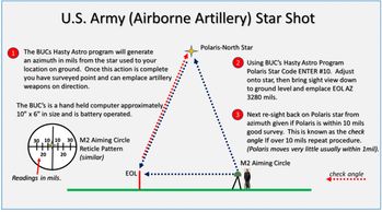
Using the M2A2 aiming circle the orienting station (OS) can utilize both the sun or stars to emplace survey in orienting the gun-line on direction of fire. This method of lay or survey is used by airborne artillery units. Extensive use of celestial survey techniques and triangulation in applied geometry. Through this extensive use in the field of military science we can exclude atmospheric lensing at higher elevations or 15 degree above the horizon. This is because this procedure is a celestial survey and is bumped or checked via another method of survey lay using grid magnetic which is less tan 1/3 of a degree 99% of the time.
Aiming Circles - Lay and Safe Circle Basics
Basic geometry as shown using circles in the field of military science. Aiming circle and safe circle are the same type of device. As shown the increments are in mils, there are 6400 mils in a complete circle. You will note some numbers are in red, this is used for when the aiming circle and safe circle bump or verify lay of survey. The mil number on the outer ring are read in. Meaning read from outside in. In this example shown the circles are bumped at 1600 mils as shown by the red arrows. On the actual circles the mils are in 100 mil increments and a micrometer knob which reads in one mil increments 0-99 mils. This completes readings in mills up to a complete 6400 mil circle. When verifying lay of circle, or as known as (BUMPING Circles) where each circle operators turn an angle on each other, circle operators rule of thumb when verifying lay is if you see RED you read RED. Methods of lay (survey) using the M2A2 aiming circle are; grid magnetic, orienting angle (OA), celestial survey, star shot, sun shot, Polaris-Kochab, and SIMO-survey transfer.
Excluding Refraction and Atmospheric Lensing at Higher Angles above the Horizon
Understanding the use of Military Sciences methods of survey and lay and the effects of refraction and lensing at higher angles that can be excluded (15 degree above the horizon). This is based on military sciences actions and validation processes in methods of lay/survey using the sun and stars. In using different methods of lay the lay circle and safe circle validate the survey when they *bump* or turn an angle on each other to check the lay of each instrument. The difference in reading must be 10 mils or less. There are 17.8 mils in one degree. Most often or 99% of the time the difference will be only 1-2 mils. This is why and how we can exclude atmospheric lensing and refraction at angles above 15-20 degrees above the horizon. The M2A2 Aiming Circle as shown. The accountability process within military science is paramount to its principles and high standard.
Using Hasty Astro Method of Lay/Survey
Hasty Astro method of lay or emplacing survey is both very accurate and can be done in relatively short period of time. This method of lay uses both sun in the day time or stars such as Polaris at night time. You will note these are extreme distances when using the sun and stars for this method of lay. Lensing and refraction are excluding at these extreme distance because of the second M2A2 aiming circle called the safe circle verifies the survey data using an alternate method of lay typically magnetic. Both circles must be within 10 mils of each other, they typically are within 1-2 mils 99.9% of the time. There are 17.8 mils in one degree.
STO and SIMO Application
The real world military science applications applied directly into STO and SIMO. The transition is exact with application and process providing solid principle and fundamentals to both STO and SIMO applications. You will note the triangulation in this application, also the 45 degree sector test box. Can you pick out the hallway walls, floor as they all come together? Remember seeing it somewhere else,
perhaps in visual perspective?
Sector Range Fans for Weapons Live Fire Ranges
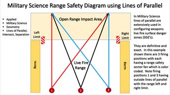
The real world military science applications applied directly relate from Military sciences real world applications. Included are uses of applied geometry for this application. There is both a manual and computerized version for determining weapons sector range fans. The computerized version is called ArGIS. Calculating and determining safety is an exact science, and there is no room for error in these applications, because lives depend on its safe practice every day. Also very important are the lines of parallel or the left and right limits, lines of intersect, they are very definitive in this application of military science. This is why military science may mention heliocentric science in some of its manuals but never apply it in its real world applications. Now see if you can pick out the visual perspective items in this and the next diagram where STO and SIMO applications were developed from.
STO and SIMO Application
Military science and visual perspective interlinked
STO and SIMO Application
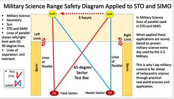
The real world military science applications applied directly into STO and SIMO. Note the key in this diagram showing STO and SIMO. The transition is exact with application and process providing solid principle and fundamentals to both STO and SIMO applications. The applications in Range Sector Fans and HASTY Astro applications both demonstrate near and extreme distances of visual perspective, which lensing and refraction can be excluded at over 15 degree above the horizon.
Visual perspective
Military science and visual perspective interlinked
STO and SIMO Application
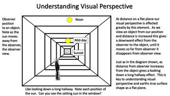
The real world military science applications are present in many things we should recognize if we just take the time to understand them. This is true with visual perspective, military science real world applications verify this as accurate. You will note the hallway, walls, and lines of parallel.
Can you pick out the lines of parallel lines of intersect, and visual perspective in the military science applications shown? This also follows visual acuity and how optics in scopes (weapons scopes-range finders-theodolites) are all designed in line with visual perspective as shown. This is why theodolites and optical scopes for weapon systems and range finders are ALL linear they correspond with visual perspective. Understanding this element is essential part in learning and the knowledge of how it we see things in our world and our visual limits. After all, human vision is one of the weakest parts of human anatomy our eyes were designed to work within this system :)).
Military science and visual perspective interlinked
Military science and visual perspective interlinked
Military Science addresses lensing/refraction and the effects on distant aiming references
The lines of visual perspective, left and right limits, lines of parallel and intersect all combine within visual perspective and are interlinked within the field of military science real world applications shown. The evidence is overwhelming once we learn how to identify it and know where to look.
Military Science addresses lensing/refraction and the effects on distant aiming references
Military Science addresses lensing/refraction and the effects on distant aiming references
Visual effects at lower elevations up to 15-20 degree above the horizon has an effect on optics and our vision. Conditions that effect this are weather, temperature, pollution, water in our atmosphere, and air density. Understanding these effects and how it can limit, lens, and effect our vision especially at long distances. Military Science identifies this and addresses it accordingly; for artillery units using distant aiming points are not to exceed 1500 meters or just under one mile in distance, when looking out at lower elevations of below 15 degree. However at higher angles for lay and safe circle procedures the skies the limit, if you can see it you can use it, meaning celestial bodies such as the sun and stars. Military Science also addresses refraction and lensing at higher angles. Meaning once the lay circle and safe circle BUMP or turn an angle on each other using alternate method of lay (survey) they must be within 10mils of each other. There are 17.8 mils in 1 degree. By doing this act on a regular basis Military Science has proven refraction and lensing at higher angles does NOT exist or is extremely minimal under 1 degree. Again this is because Military Science has a high degree of accountability because lives depend on it every day.
Military Science References
Military Science Fundamentals
The list of military manuals as references for this information are;
1. The U.S. Army, Tactics, Techniques, and Procedures for Corps Artillery, Divisional Artillery, and Brigade Artillery, Artillery Training Planner, ATP 3-09.24, dated 21 November 2012.
2. The U.S. Army Training Circular (TC), Field Artillery Manual Cannon Gunnery, TC 3-09.81, dated April 13, 2016.
3. U.S. Army, Artillery Survey Operations, Field Manual Tactics, Techniques, and Procedures for Field Artillery Survey Operations, FM 6-2, dated 23 September 1993.
4. U.S. Army Field Artillery Cannon Battery Operations Field Manual, FM 6-50, dated 23 December 1996.
5. U.S. Army Artillery Training Planner, The Field Artillery Cannon Battery, ATP 3-09.50 manual dated May 2016.
6. U.S. Army Map Reading, Field Manual, FM 3-25.26 dated January 2005.
7. U.S. Army Developmental Test Command Test Operations Procedure, Test Operation Procedure 03-2-709, dated 19 November 2010.
8. The U.S. Army, Field Artillery School, Ft. Sill. Oklahoma, The Special Text ST 6-50-20 Executive Officer/Platoon Leader Handbook Cannon Artillery, dated 20 February 1998.
9. Department of the Army, DA-PAM 385-63 Range Safety, dated 10 April 2003.
10. Department of the Army Regulation, AR 385-63, Range Safety (MCO 3570.1C), dated
30 January 2012.
11. The U.S. Army Field Manual FM 3-09.8 Field Artillery Gunnery, dated July 2006.
Military Science Fundamentals
Military Science Fundamentals
The strategic and fundamental accuracy of military science is vital, lives depend on its safe use and practice every day, and because second place in military science can get you conquered.
Military Science links
1. Setting up the M2Aiming Circle
2. Declinating the M2 Aiming Circle
3. Performing Hasty Traverse M2 Aiming Circle
4. Performing HASTY ASTRO SUN /STAR SHOT using the M2 Aiming Circle
5. Magnetic Checks using M2 Aiming Circle verifying lay of survey using grid magnetic
Other Military Science Applications
Military Science weapons bore-sighting
The U.S. military weapons bore-sighting is another solid military science application which uses extensive use of line of parallel when bore-sighting larger weapon systems such as artillery and armor. You will note in the diagram above the weapon cannon tube and gunners sight are in line of parallel designated by the black arrows. In bore-sight procedures the gunner can adjust the weapons sight azimuth and elevation in towards the cannon tube (shown by blue arrow) to achieve correct weapons bore-sight but cannot EXCEED the line of parallel as (show by the red arrow). These processes and applications of military science are absolute in their methodology and principle. Depending on the specific weapon system will determine bore-sight distances. There are also different methods of bore-sight as shown here (target method or field method) for artillery.
Military Science Live Fire Range Safety Box and Limits
The defined limits used in military science application and set up of live fire range safety box. Safety boxes are designed as limits for artillery rounds to impact in. The safety box is comprised of near - far and left - right limits. Left and right limits are azimuths set by deflection, and the near and far limits are set as quadrants. This limits are definitive and are required for safe accurate indirect live fires for artillery weapon munitions impact area. The impact area is the designated area where the explosive rounds will land safely. The safety box is created by the artillery unit fire direction center (FDC) "within" the designated impact area for high explosive munitions to impact into.
Military Science Artillery Range Safety T
Military Science Artillery Range Safety T
Military science application for artillery live fire range safety T. This document is used as a safety limit for weapons live indirect artillery fire. This document lists the weapons left and right limits, maximum and minimum quadrants, high angle, low angle, shell, fuze combination, charge, firing position/location, and azimuth of fire. The Safety T provides a reference guide for the gun crew to safely fire the weapon into a impact area. Sometimes lines of parallel in real world military science applications are not always lines but a sequence of numbers. Will give an example of its use. A fire mission is given to the gun crew with the following information, the section chief must determine if it is safe to fire;
Fire mission gun one, shell HE, fuze PD, charge 6 WB, deflection 3270, quadrant 339. Is this fire mission is safe to fire? Yes, the defection numbers given fall between the guns left 3390 and right 3250 low angle limit, the quadrant also falls between max 685 and minimum 288 quadrant elevations, the shell-fuze -charge combination are all in accordance with the safety T. Now will give a another example see if you can determine if the fire mission is safe to fire for gun one. Gun one fire mission High Angle, shell illumination, fuze time, time 15.6, charge 5 GB, deflection 3190, quadrant 1075. Is this fire mission safe to fire? Review the high angle safety T information given. The answer is no, the mission is not safe to fire, the deflection given 3190 exceeds the guns left limit of 3180 by 10 mils. All other information given is safe. This is an example of exceeding the line of parallel in military science.
Interviews and Conferences
The display at the 2021 Solar Return Event

The 2021 Solar Return Festival held in Greenville, South Carolina was another amazing flat earth event. This event was centered around the return of the sun on its return from the equator to the northern prime meridian the Tropic of Cancer from its long journey from the southern most prime meridian the Tropic of Capricorn.. Corey at the display which shows the Marx Device. Subject areas on display and explained were Operation Resolute Time 2020, Military Science applications, orienting station setup and digital protractor, use of the sun, in determining earths true surface shape, emplacement of the sun survey position using the Marx Device. Special thanks to Karen B for all her hard work and efforts who coordinated the Solar Return event.
The International Truth Expo 2025 Quartzite Arizona

The 2025 International Truth Expo held in Quartzite, Arizona. Guest speaker Corey Kell gives presentation on using the sun to determine earths true surface shape.
Corey's Interview at the 2019 Dallas Texas International Flat Earth Conference

Corey does interviews, this one at the 2019 Flat Earth International Conference which was held in Dallas, Texas. This interview team was from Live Through Productions. So many positive minded people, the flat earth community is like family.
The 2021 Flatoberfest Presentation

The 2021 Flatoberfest conference in Spartanburg, South Carolina.